


Headquarters Address: Building 3, Science and Technology Innovation Park, No. 311 Yanxin Road, Huishan District, Wuxi City
Email: sales@witlink.cn
Phone: 0510-83880511
Website: www.witlink.cn
Introduction and Classification
The north finder is a type of compass used to find the true north direction value of a certain location. The gyroscope north finder, also known as the gyroscope compass, is an inertial measurement system that uses the principle of gyroscope to determine the projection direction of the Earth's rotational angular velocity on the local horizontal plane (i.e. true north position). Its search for north does not require external reference. Except for being limited by high latitude, its north finding measurement is not affected by weather, day and night time, geomagnetic field, and site visibility conditions. A gyroscope north finder is a precision inertial measurement instrument commonly used to provide azimuth reference for mobile weapon systems such as artillery, ground to ground missiles, and ground radars. According to the type of gyroscope used, gyroscope north finders can be divided into the following three types:
A north finder using a two degree of freedom gyroscope as the Earth's rotation sensor (such as a suspended pendulum gyroscope north finder)
A north finder using a single axis rate gyroscope as a sensor (such as a strapdown gyroscope north finder)
Platform North Search System
The gyroscope north finder is extremely sensitive to environmental vibration interference, especially low-frequency vibration interference. According to the usage environment, gyroscope north finders can be divided into three types: high-precision ground mounted north finders, vehicle mounted gyroscope north finders, and ship mounted dynamic base gyroscope north finders.
Fiber optic gyroscope north finder is a high-precision inertial instrument that autonomously indicates azimuth. It can provide the angle between the carrier and true north direction without inputting latitude values. The Earth's rotation rate measured by fiber optic gyroscope and the angle between the gyroscope and the horizontal plane measured by accelerometer can be calculated by computer to obtain the angle between the baseline of the carrier and the true north direction. The accelerometer placed on the baseline can measure the attitude angle of the north finder.
The fiber optic gyroscope used in the fiber optic gyroscope north finder is a solid-state device without a rotating part, so it can withstand impact and vibration. This is something that other non fiber optic gyroscopes cannot achieve. This article mainly introduces the application of fiber optic gyroscope in north finder.
Working Principle
Principle of Fiber Optic Gyroscope North Finder
Fiber Optic Gyroscope (FOG) is a new type of all solid state gyroscope based on Sagnac effect. It is an inertial measurement element without mechanical rotating parts, with advantages such as shock resistance, high sensitivity, long lifespan, low power consumption, and reliable integration. It is an ideal inertial device in the new generation of strapdown inertial navigation systems.
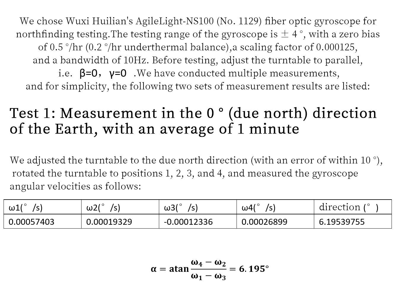
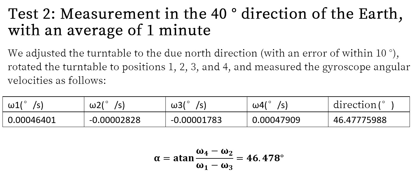
In fiber optic gyroscope based north finding applications, the majority of methods used involve FOG rotation at a fixed angle and calculating the angle relative to the north direction by determining the offset. In order to accurately point north, it is also necessary to eliminate the drift of FOG. Generally, a rotating platform as shown in Figure 1 is used to place the fiber optic gyroscope on a moving base, with the plane of the moving base parallel to the horizontal plane and the sensitive axis of the fiber optic gyroscope parallel to the plane of the moving base. When starting to search north, the gyroscope is in position 1, and its sensitive axis is parallel to the carrier. Assuming that the angle between the initial direction of the sensitive axis of the fiber optic gyroscope and the true north direction is α. The output value of the gyroscope at position 1 is ω 1; Then rotate the base 90 ° and measure the output value of the gyroscope at position 2 as ω 2. Rotate 90 ° twice in sequence, turning to positions 3 and 4 respectively, to obtain angular velocities ω 3 and ω 4.
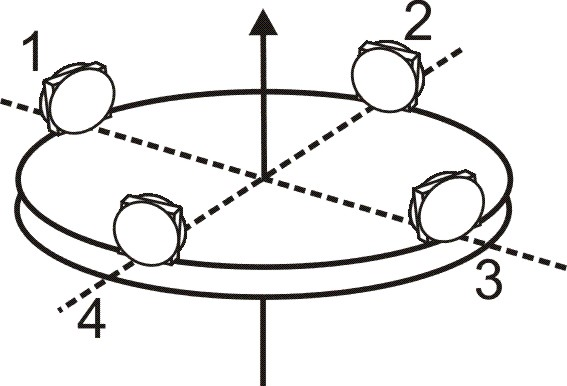
Figure 1 Schematic diagram of gyroscope north finding
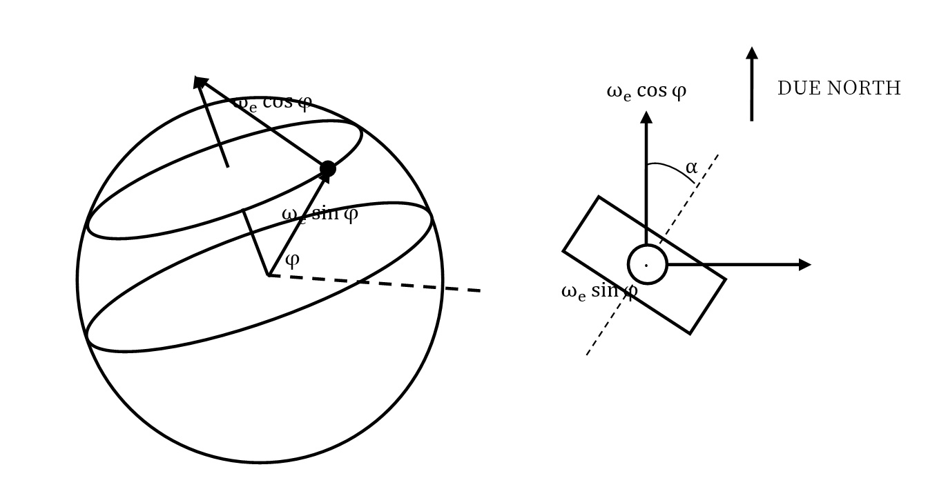
Figure 2 Projection of the Earth's rotation on the sensitive axis of the gyroscope
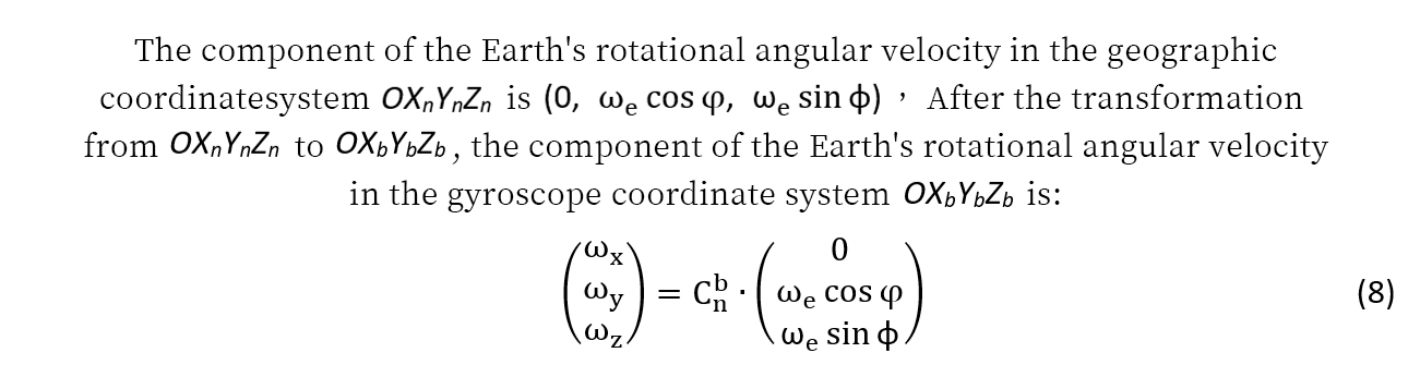
Assuming the latitude of the measurement point is φ and the rotation of the Earth is ωe, the angular velocity measured at position 1 is:

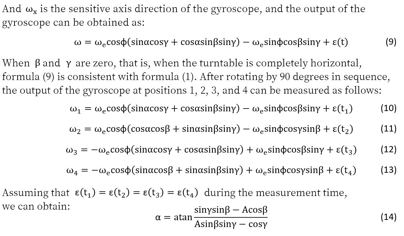
Among them, ε (t1) is the zero drift of the gyroscope output. Similarly, it can be concluded that:

In a short period of time, assuming that the drift of the fiber optic gyroscope is a constant, i.e.: ε(t1)=ε(t2)=ε(t3)=ε(t4), then


By using this method for measurement, the zero bias of the gyroscope can be eliminated, and there is no need to know the latitude value of the measurement location. If the latitude of the measurement location is a known value, then only measuring positions 1 and 3 (or 2 and 4) can determine the heading angle.
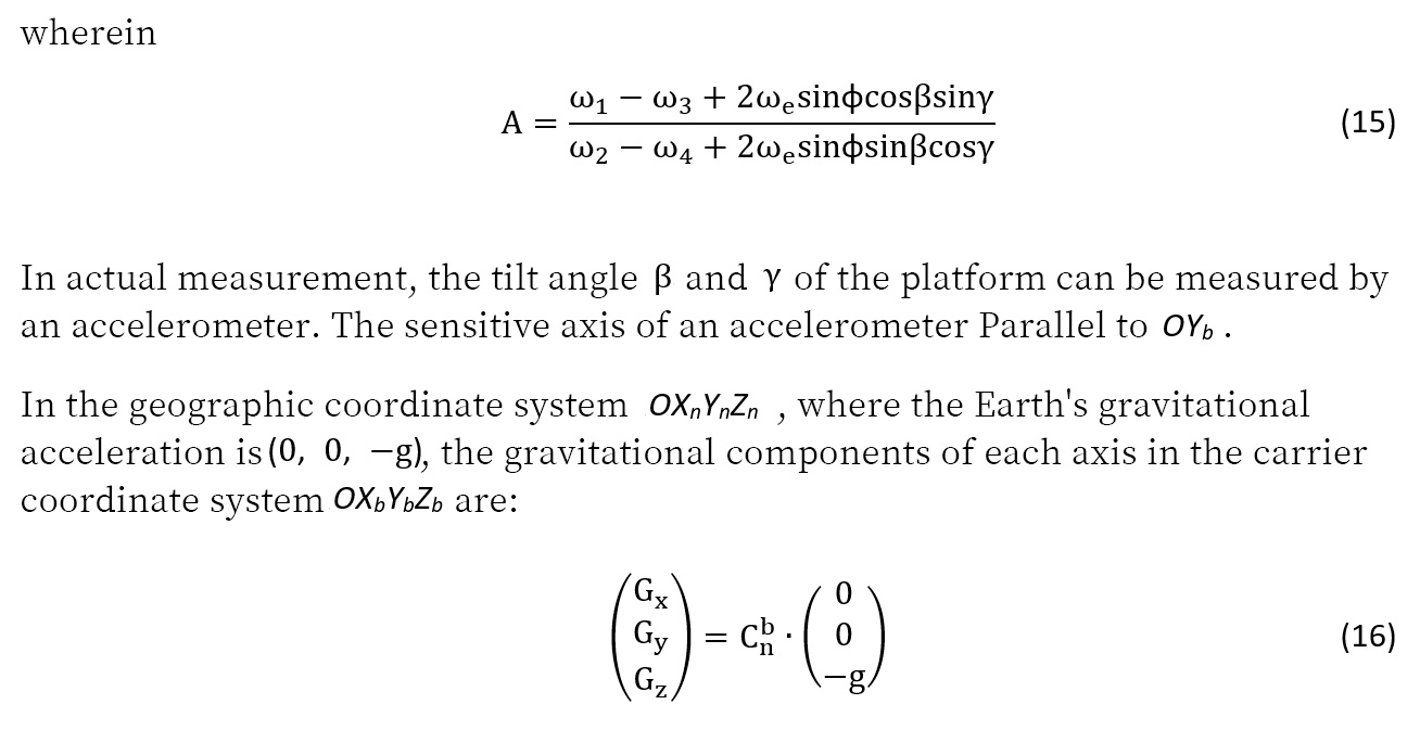
The Influence of Base Tilt on North Finding Accuracy
The above analysis is based on the horizontal plane of the moving base, that is, the sensitive axis of the fiber optic gyroscope is in the horizontal plane. If there is a significant inclination angle between the base plane of the gyroscope and the horizontal plane, the accuracy of north finding will be greatly affected. The following analysis examines the impact of inclination angle on the measurement of azimuth angle when the base plane is not horizontal.
Let the attitude angles of the carrier be α, β, and γ, representing heading angle, tilt angle, and pitch angle, respectively. Establish the following coordinate system:
1) The geographic coordinate system OXnYnZn has directions of east, north, and sky, as shown in the left figure of Figure 3.
2) The OX1Y1Z1 coordinate system is obtained by rotating the coordinate system OXnYnZn counterclockwise around the Zn axis at an angle of α.
3) The OX2Y2Z2 coordinate system is obtained by rotating the coordinate system OX1Y1Z1 counterclockwise around the X1 axis at a β angle.
4) The carrier coordinate system OXbYbZb is obtained by rotating the coordinate system OX2Y2Z2 counterclockwise around the Y2 axis by a gamma angle. OXb, OYb, OZb are the horizontal and normal directions of the carrier's front and rear lines, respectively. The longitudinal axis of the carrier coincides with the OXb axis, and the gyroscope coordinate system coincides with it, that is, the gyroscope sensitive axis coincides with the OXb axis, as shown in the right figure of Figure 3.
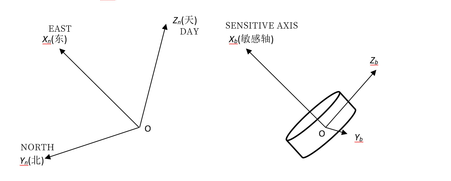
Figure 3 Geographic coordinate system and carrier coordinate system
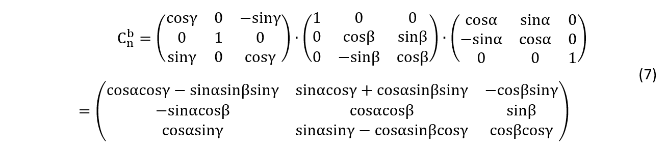
The transformation matrix from the geographic coordinate system OXnYnZn to the gyro coordinate system OXbYbZb can be obtained as follows:
Ultra High Precision Tilt Sensor_SIS2000 Ultra High Precision Tilt Sensor Accuracy

Dual axis tilt sensor L_LS226 low-cost dual axis tilt sensor with an accuracy of 0.2 °

Dual axis tilt sensor _SS328 Dual axis tilt sensor current output accuracy of 0.1 °
Tiltmeter, Dual Axis Tiltmeter Sensor, LS326 Digital Accuracy 0.1 °